Electrical Schematics
LOBBYIST
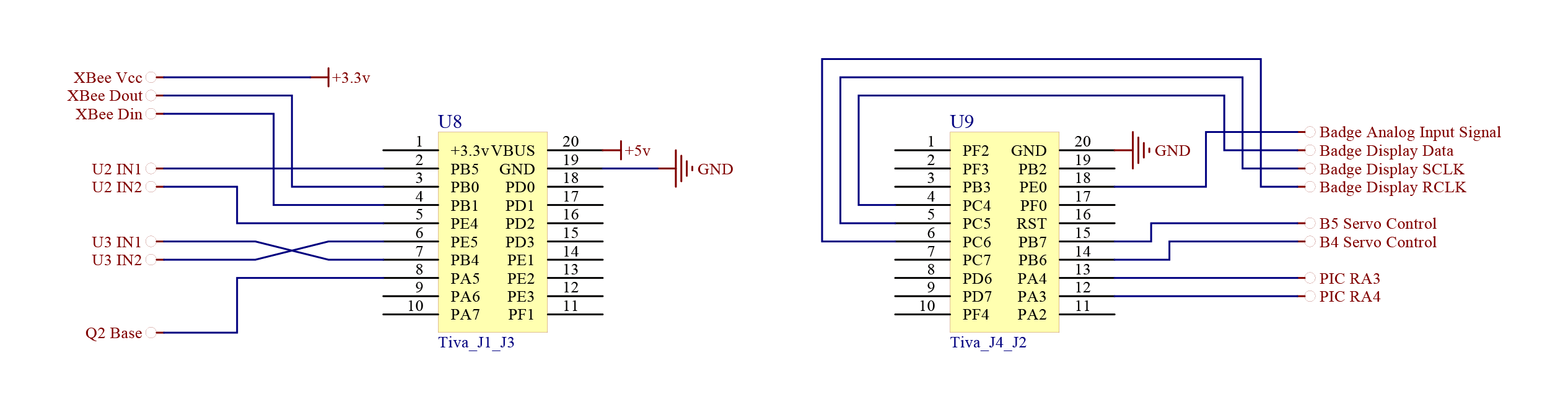
LOBBYIST - Tiva Interface
The Tiva microcontroller on the LOBBYIST communicates wirelessly with the controller via XBee radios.
Power Distribution and Lift Fan Control
The power board consists of two 7.2-volt NiCd batteries wired in parallel for the thrust fan motors, and two NiMH batteries wired in series for the lift fan, with voltage regulators for the Tiva microcontroller and XBee radio.
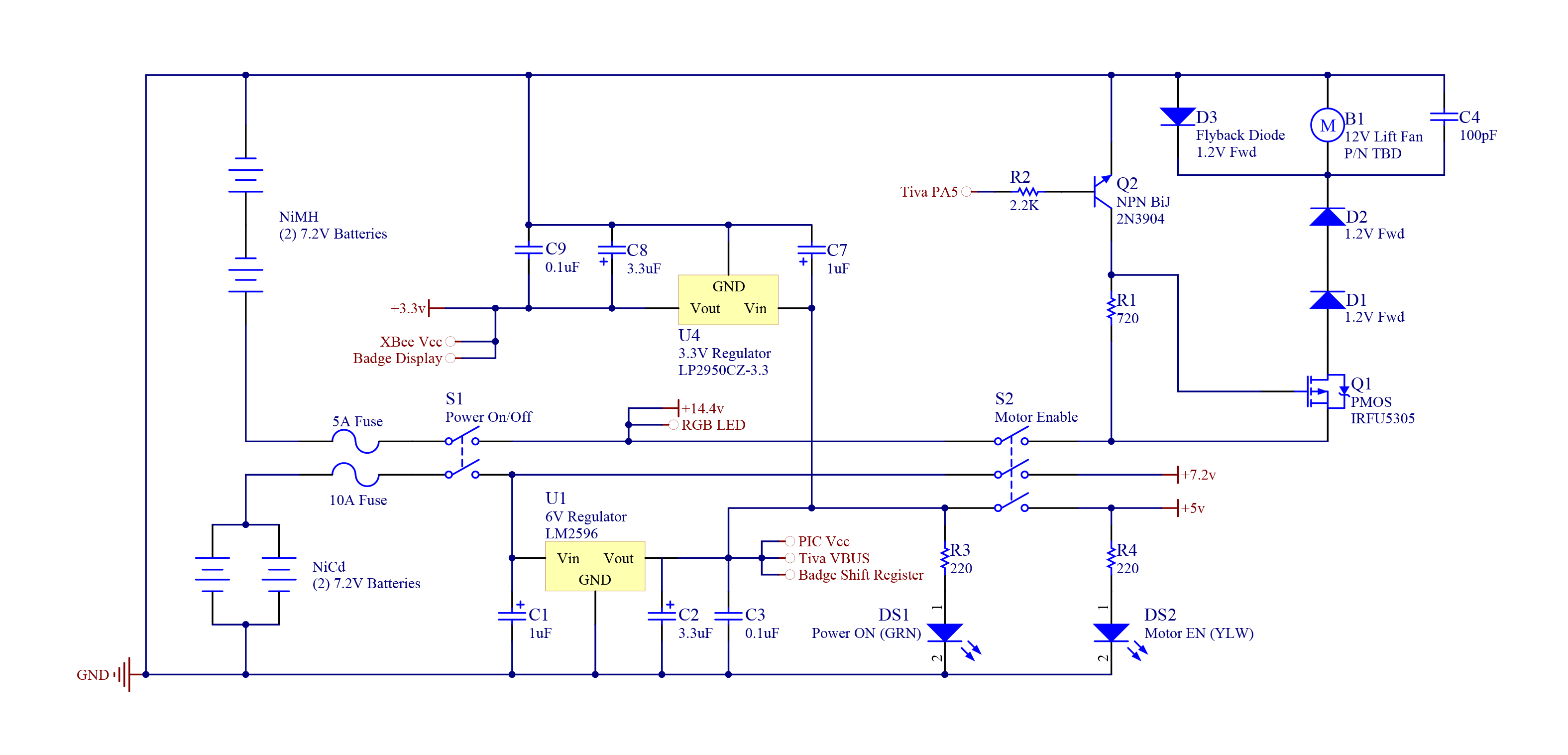
Motor Control
All of the servos used a 5V line and the brushed DC motors that were used to maneuver the hovercraft used a 7.2V line.

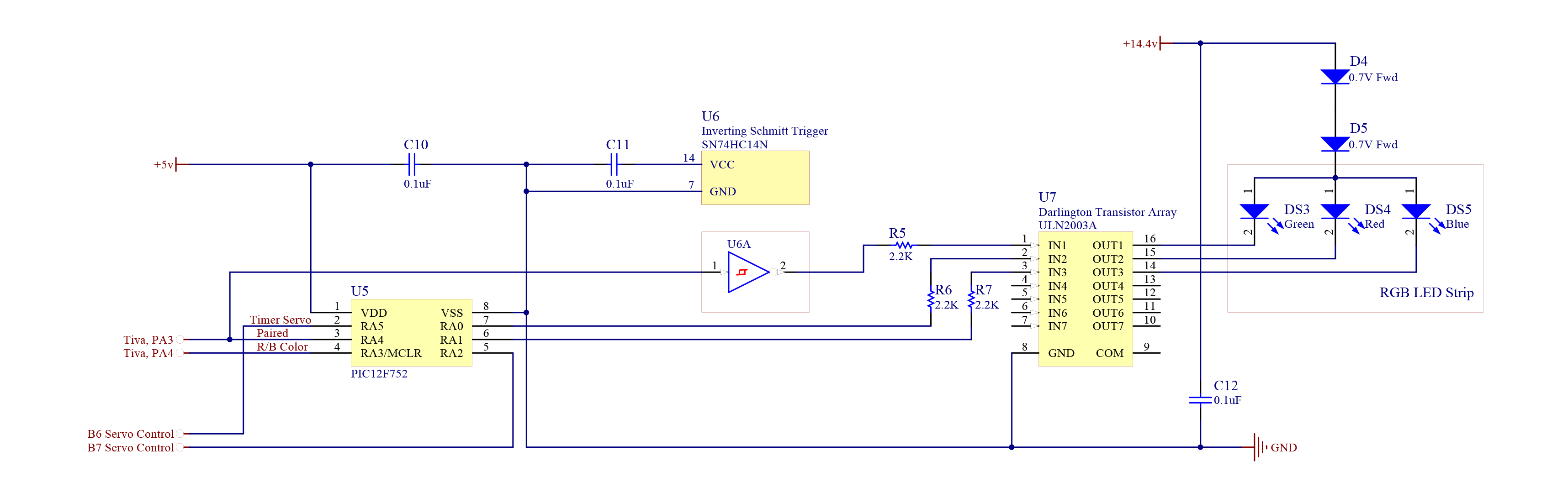
DMC Interface and LED Control
The DMC onboard the LOBBYIST uses a ULN2003A to turn on the LED strips, along with actuating the servos.
Badge Input and 7-Segment Display
The supplied badge was used by the LOBBYIST to determine which number it was bestowed for the controllers to pair with. A 7-segment display was implemented to give the audience another indication of which team number the LOBBYIST currently had.
PAC
PAC - Tiva Interface
The Tiva microcontroller provides the means of communication for the PAC using a wireless XBee radio. The Tiva also handles the GPIO for sensing, switches, and LED outputs.

Power
The power distribution for the PAC uses a single 7.2V NiCd battery to supply power for the sensors, switches, and LEDs, as well as the XBee and Tiva which are all housed inside the PAC. With the supplied battery, the PAC has a guaranteed life of at least 10 continuous hours of operation. The calculations for this result can be followed in the linked Excel spreadsheet or PDF file.

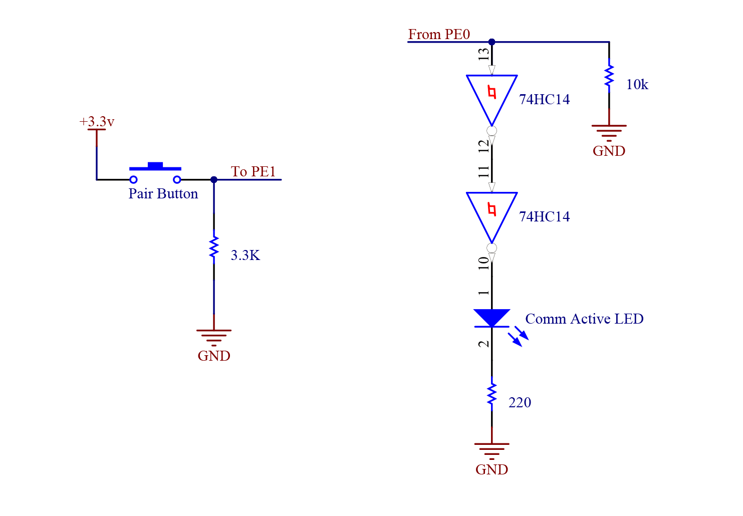
Pairing
The pair status LED receives a signal from the Tiva microcontroller when a pairing event is aknowledged in order to guarantee that there is active communication between the PAC and LOBBYIST.
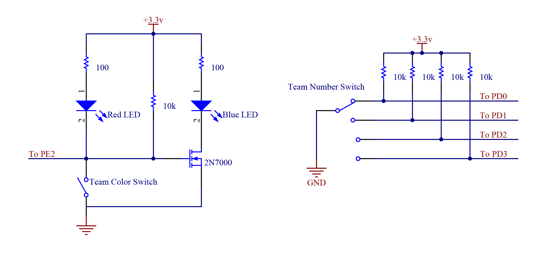
Team Select Switches
The switches on-board the PAC were used to select and indicate the color of the current team the user is playing for, and the LOBBYIST number it will attempt to pair with.
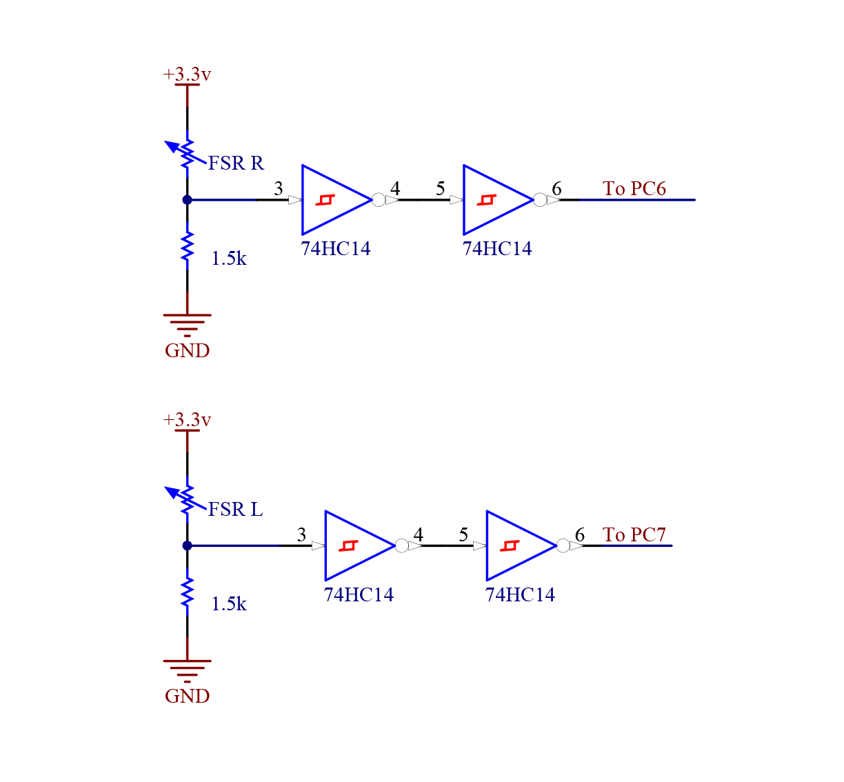
Force Sensors
The force sensitive resistors (Pololu 1645) were placed on the helmet so that when a person controlling the hovercraft needed to reverse, he or she would have to hit the sides of the helmet in order to cause the voltage divider to induce an output high across the pair of Schmitt triggers for the Tiva microcontroller to process as a reverse command and transmit it to the LOBBYIST.
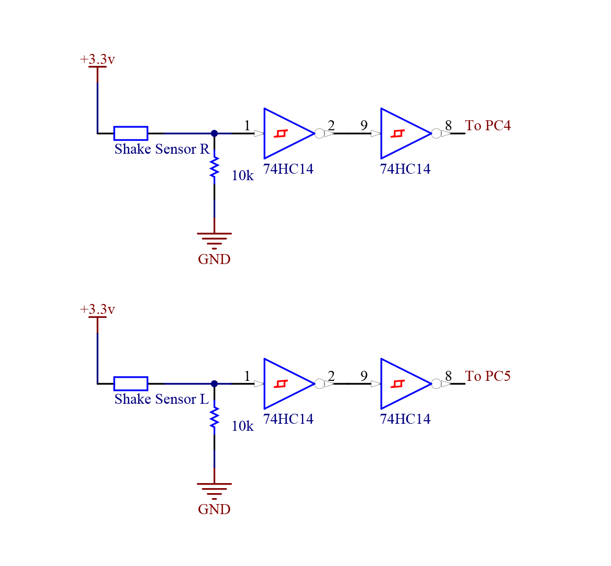
Shake Sensors
The shake sensors (Adafruit 1766) in the PAC flippers were spring actuated switches that were pulled down and passed through a pair of Schmitt triggers. Once the correct sensors were found (fast/most sensitive), they were dampened and put in a robust casing. The inputs had to be tuned on the receiving end in order to make the driving simpler.
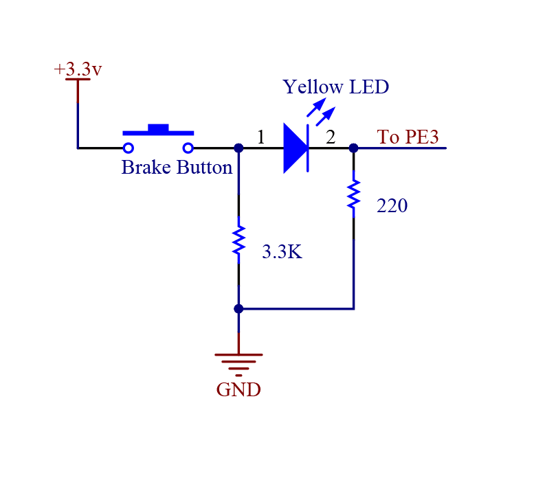
Brake Button
The brake button was our most straight-forward input, allowing the person in control of the LOBBYIST to quickly brake in case the hovercraft was about to crash, or simply prevent excessive drifting or spinning out of control. The yellow LED was used to provide feedback to the operator.